+86 0755 2301 1202
info@mightyling.com
Building 1, Zhongzhan Technology Park, No. 9 Furong Road, Tantou Community, Songgang Street, Shenzhen
This page explains a clear, repeatable workflow for designing an LED display system. It covers site requirements, module and cabinet planning, pixel and area calculations, receiving card sizing, and a basic price formula. Use the example of an 8.0 m × 6.0 m P10 display to validate the method.
Collect these client constraints up front:
Required visible area (width × height).
Target pixel pitch (e.g., P10).
Budget range.
Installation environment (indoor/outdoor), viewing distance, and mounting method.
Example: target area 8.0 m × 6.0 m, pixel pitch P10.
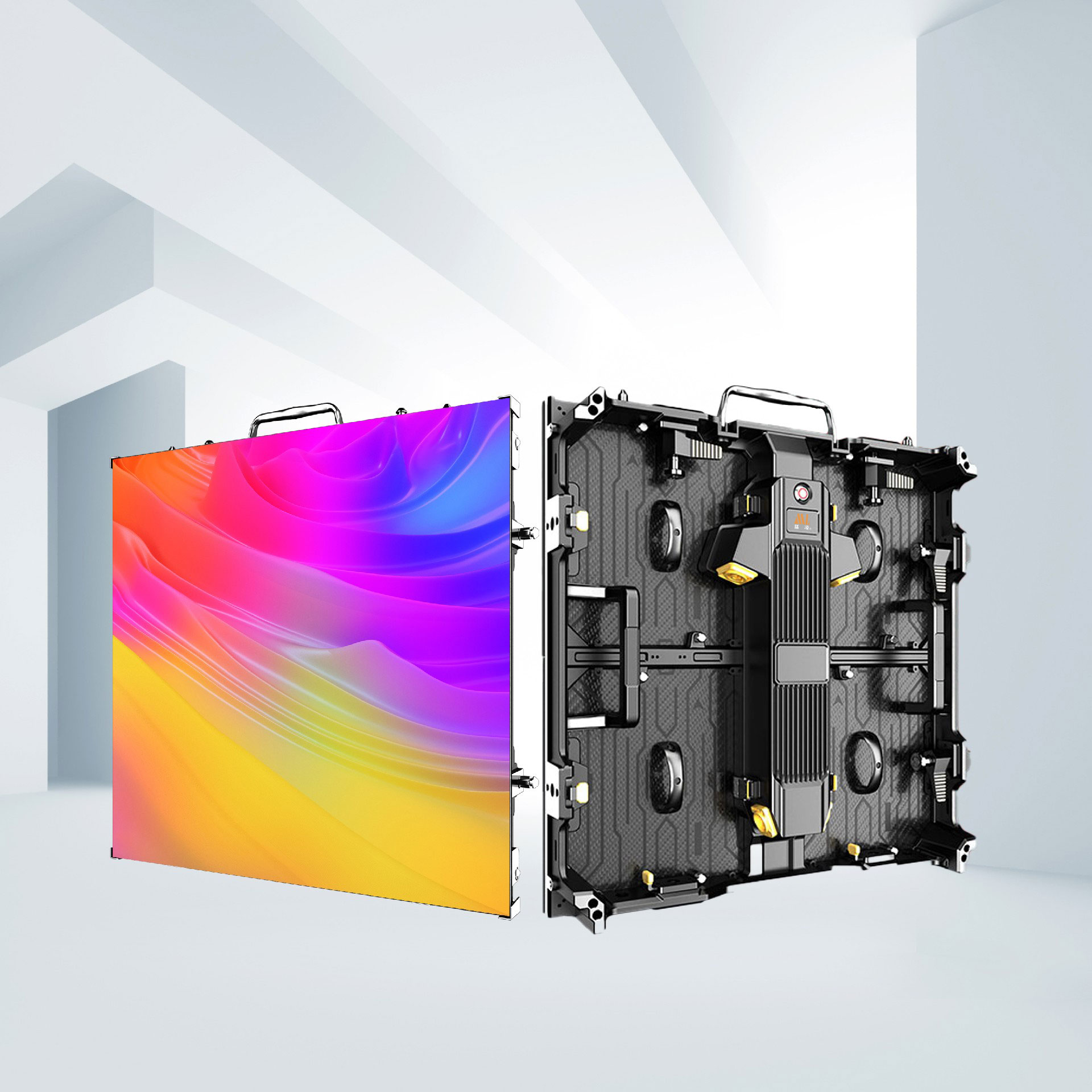
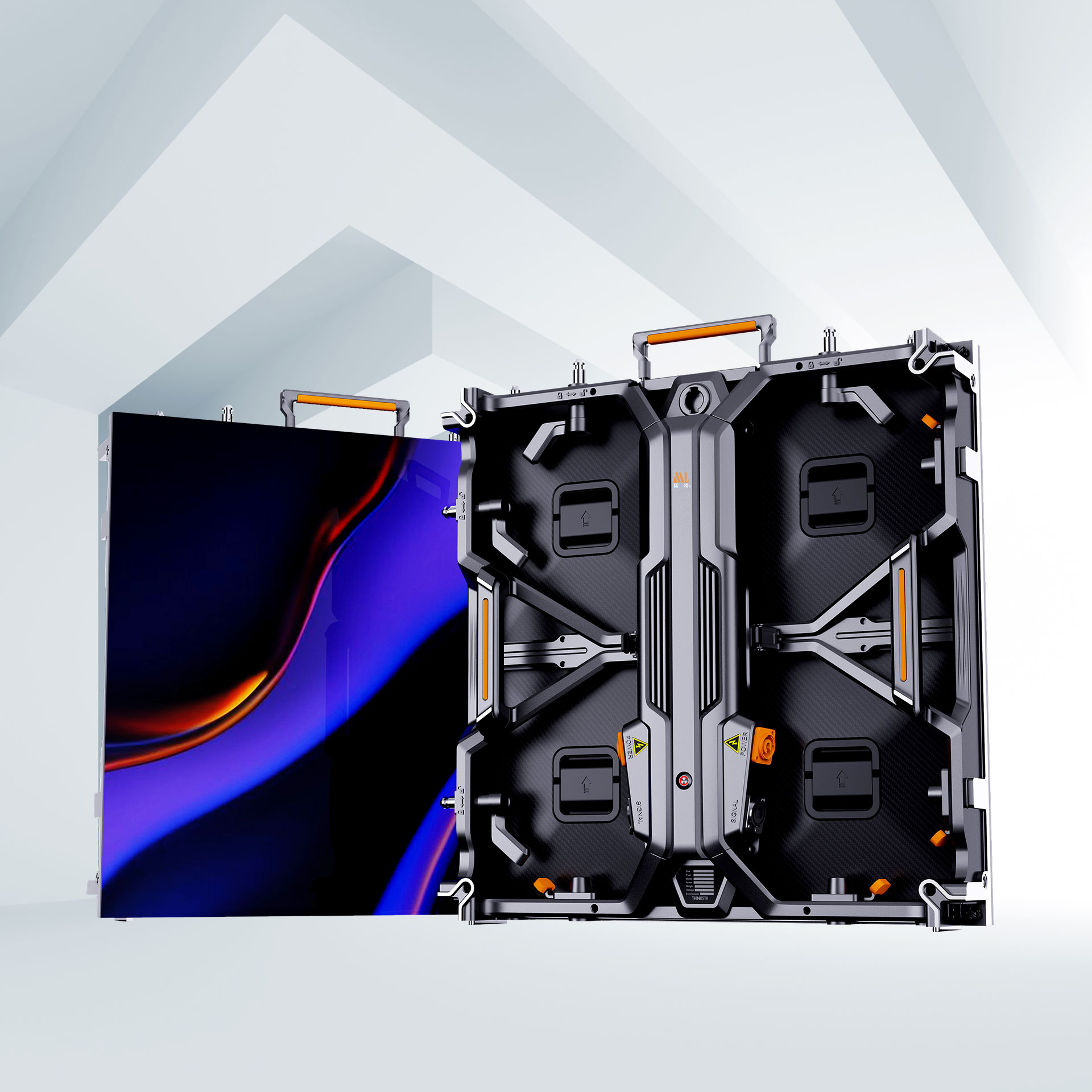
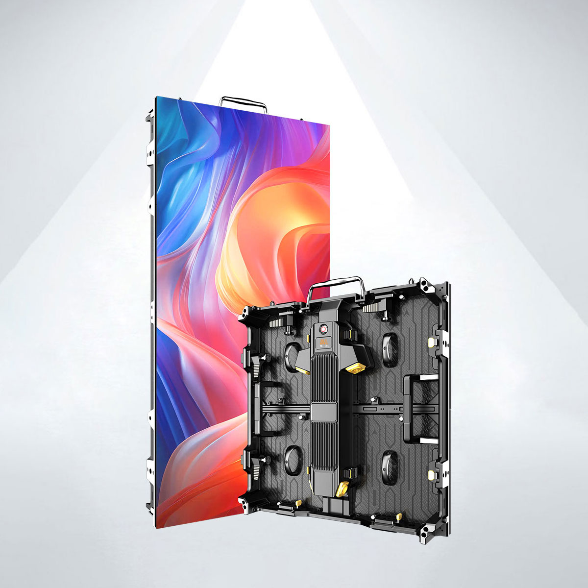
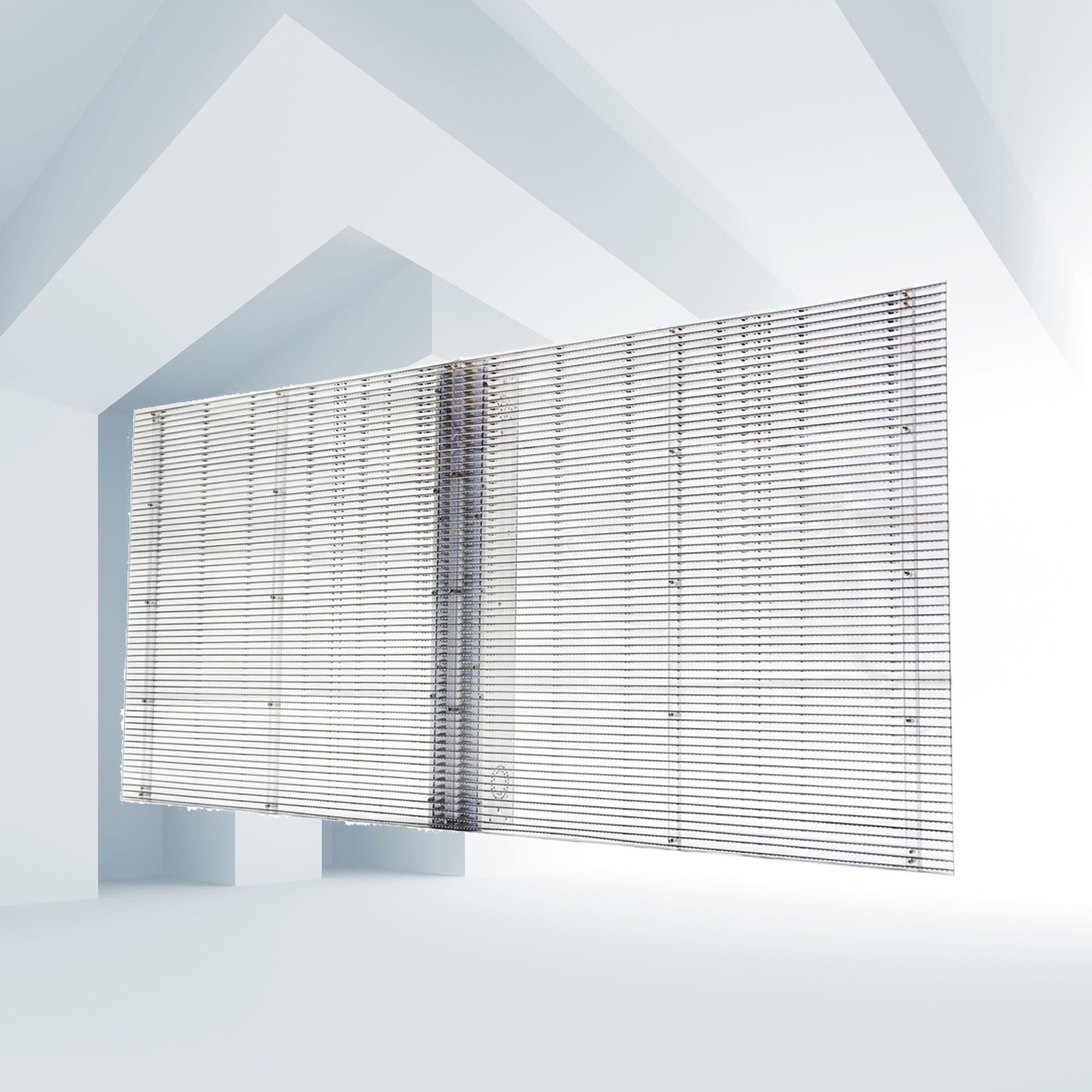
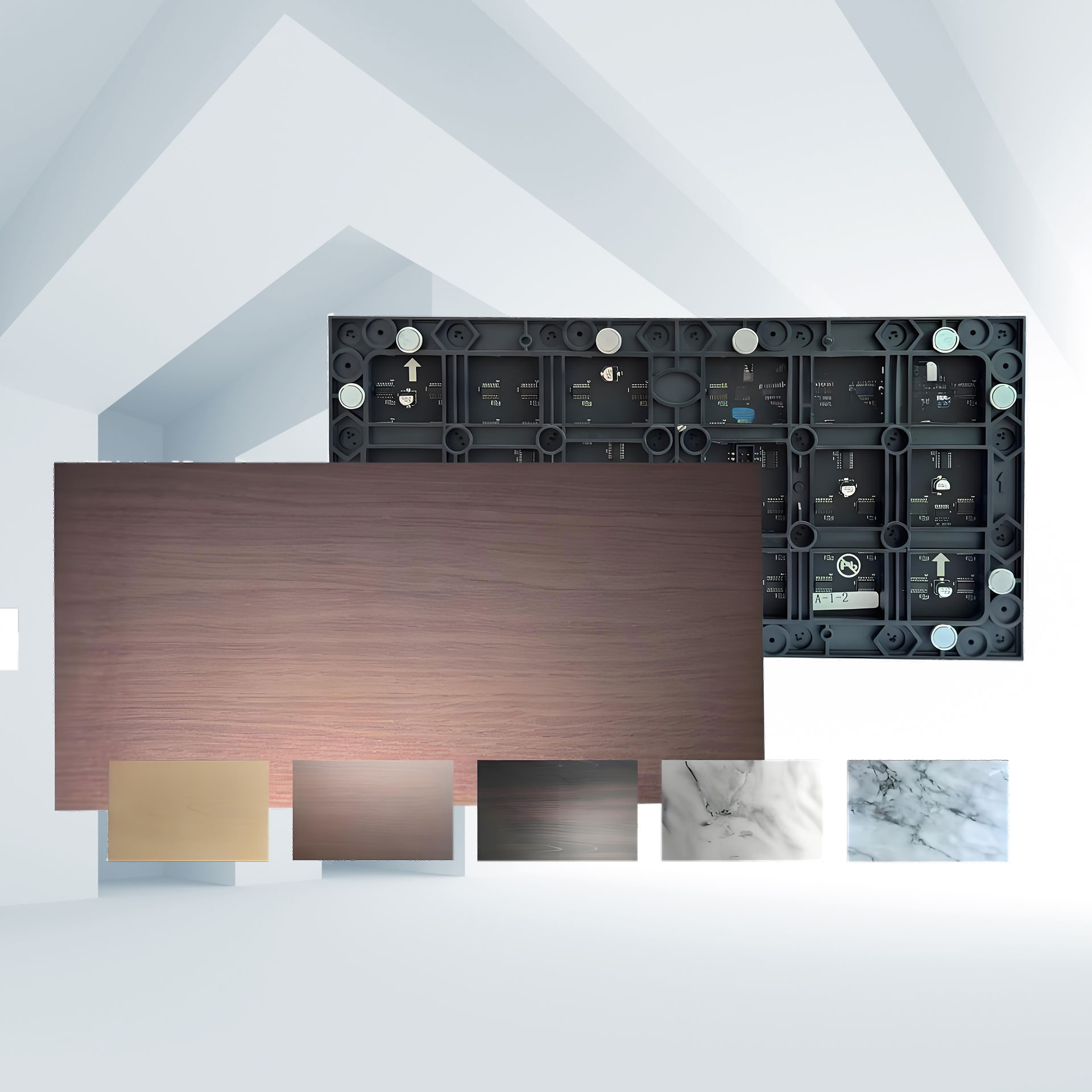
Document the physical and electrical specs of the chosen LED module and cabinet.
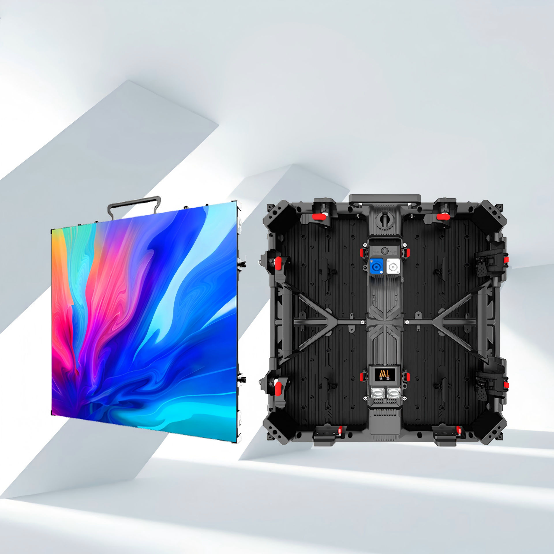
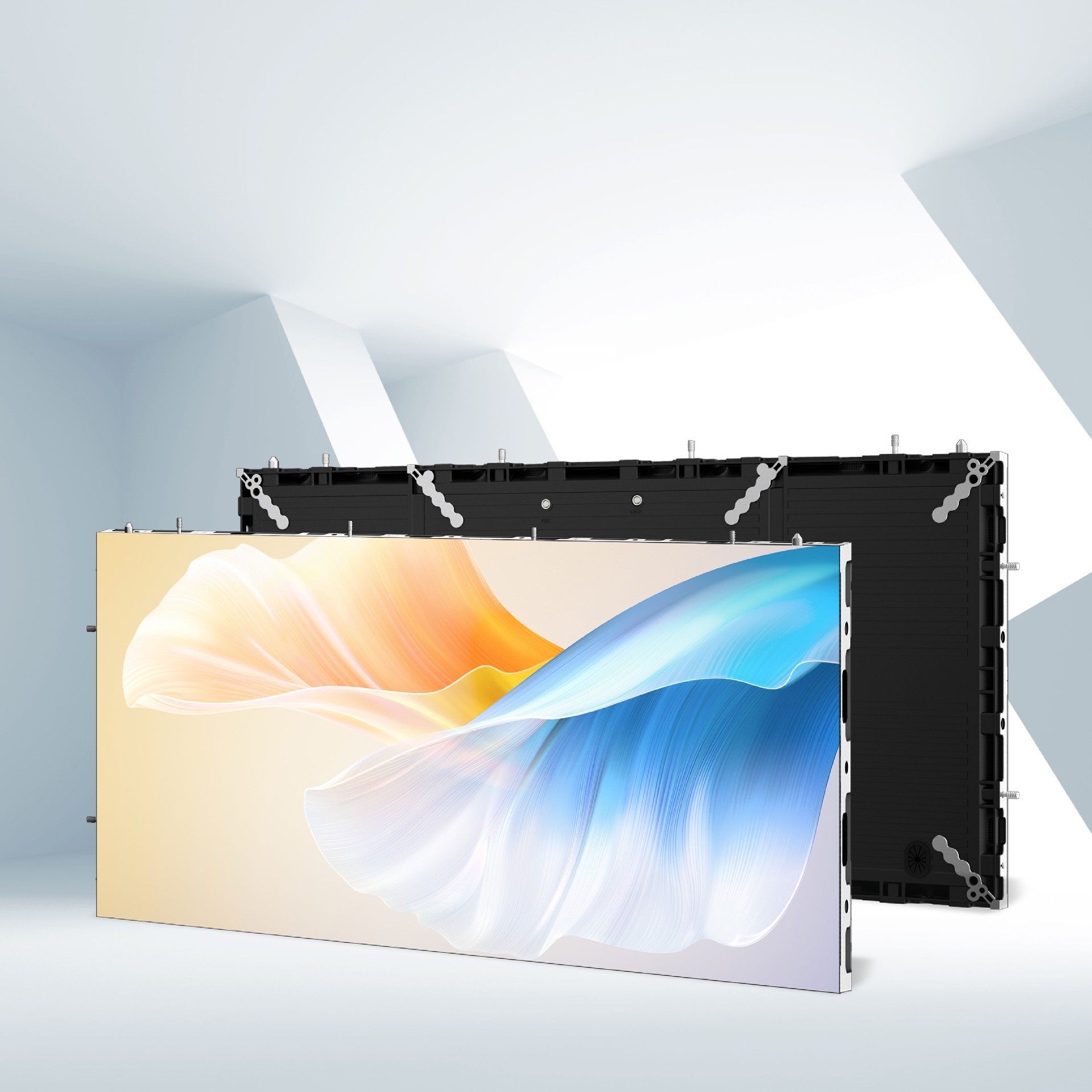
Module size and resolution (e.g., P10 module 160 mm × 160 mm, 16 × 16 pixels).
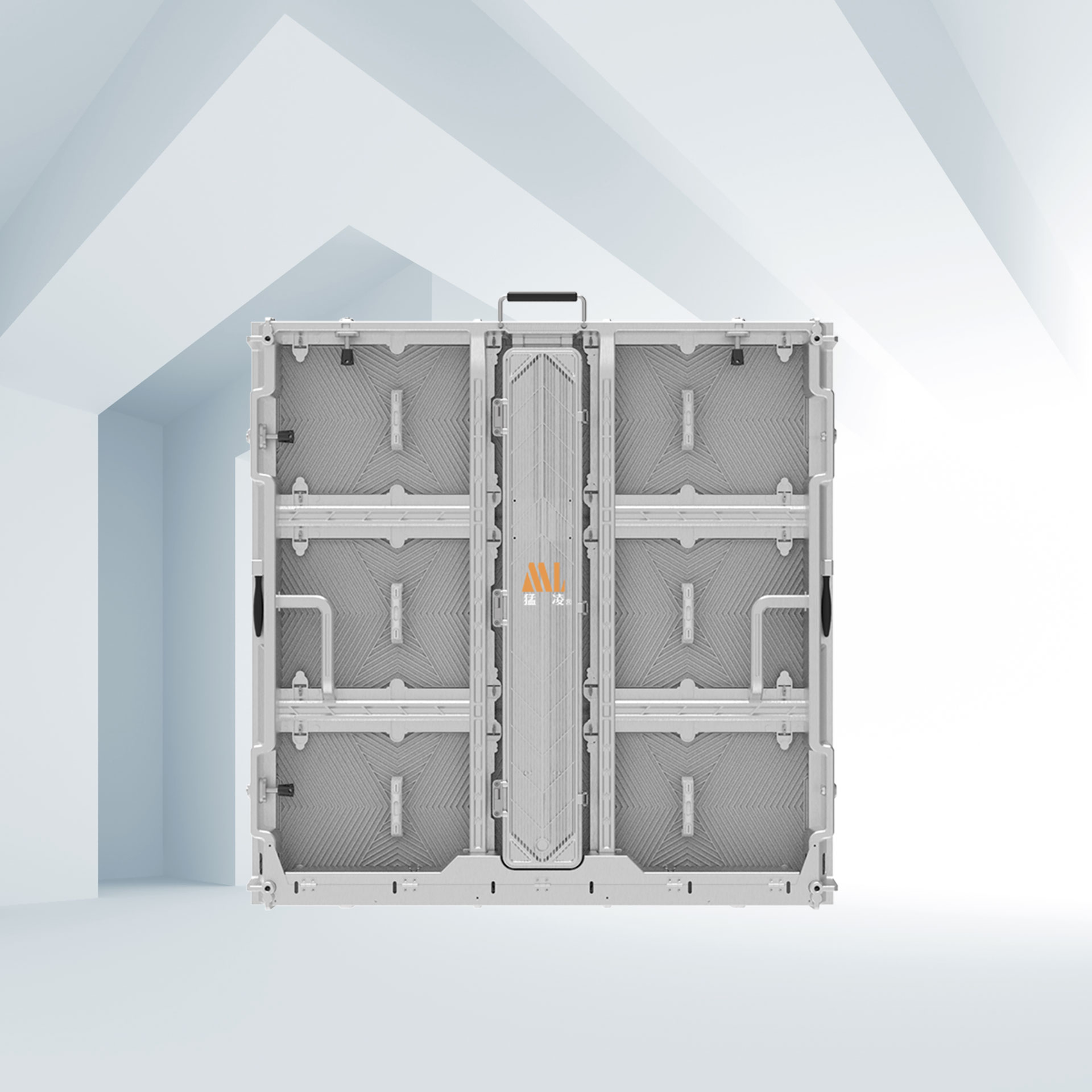
Cabinet (box) dimension and packaging format (e.g., cabinet 640 mm × 960 mm, packaging 4 × 6 modules per cabinet).
Cabinet weight, mounting points, power per cabinet, ingress protection (IP rating), and cooling requirements.
Convert desired display dimensions to module counts along width and height.
Formulas:
NL = display_width / module_width
NH = display_height / module_height
Example (module 0.16 m = 160 mm):
NL = 8.00 / 0.16 = 50 → choose 48 to match cabinet packaging.
NH = 6.00 / 0.16 = 37.5 → choose 36 to match cabinet packaging.
Notes:
Adjust counts to match cabinet packaging (here 4 × 6 modules per cabinet).
Choose the nearest module count divisible by the cabinet layout.
Compute actual installed area from chosen module counts.
S = module_width × NL × module_height × NH
Example:
S = 0.16 × 48 × 0.16 × 36 = 44.2368 m²
Report actual installed area to client. Include tolerance and visible active area vs. cabinet outer dimensions.
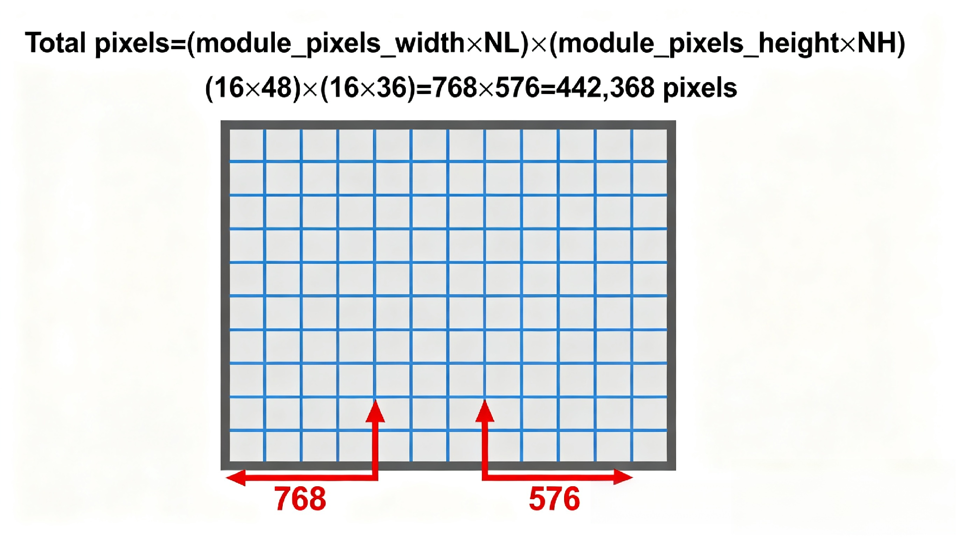
Compute total pixels from module resolution and module counts.
Total pixels = (module_pixels_width × NL) × (module_pixels_height × NH)
Example (module 16 × 16 pixels):
Horizontal pixels = 16 × 48 = 768
Vertical pixels = 16 × 36 = 576
Total pixels = 768 × 576 = 442,368
Determine number of receiving cards required. Use the receiver capacity rating (common example: one receiver controls up to 256 × 128 pixels).
Steps:
Take horizontal and vertical pixel counts.
Divide each by the receiver block size limits or treat capacity as total pixel budget per card (256 × 128 = 32,768 pixels per card).
Round up to nearest integer and multiply to get total card count.
Example method (capacity per receiver = 256 × 128):
Receiver capacity = 256 × 128 = 32,768 pixels
Required receivers = ceil(Total pixels / Receiver capacity)
Required receivers = ceil(442,368 / 32,768) = ceil(13.5) = 14 receivers
Confirm with vendor whether receivers address contiguous rectangular blocks and how mapping is done for your control system.
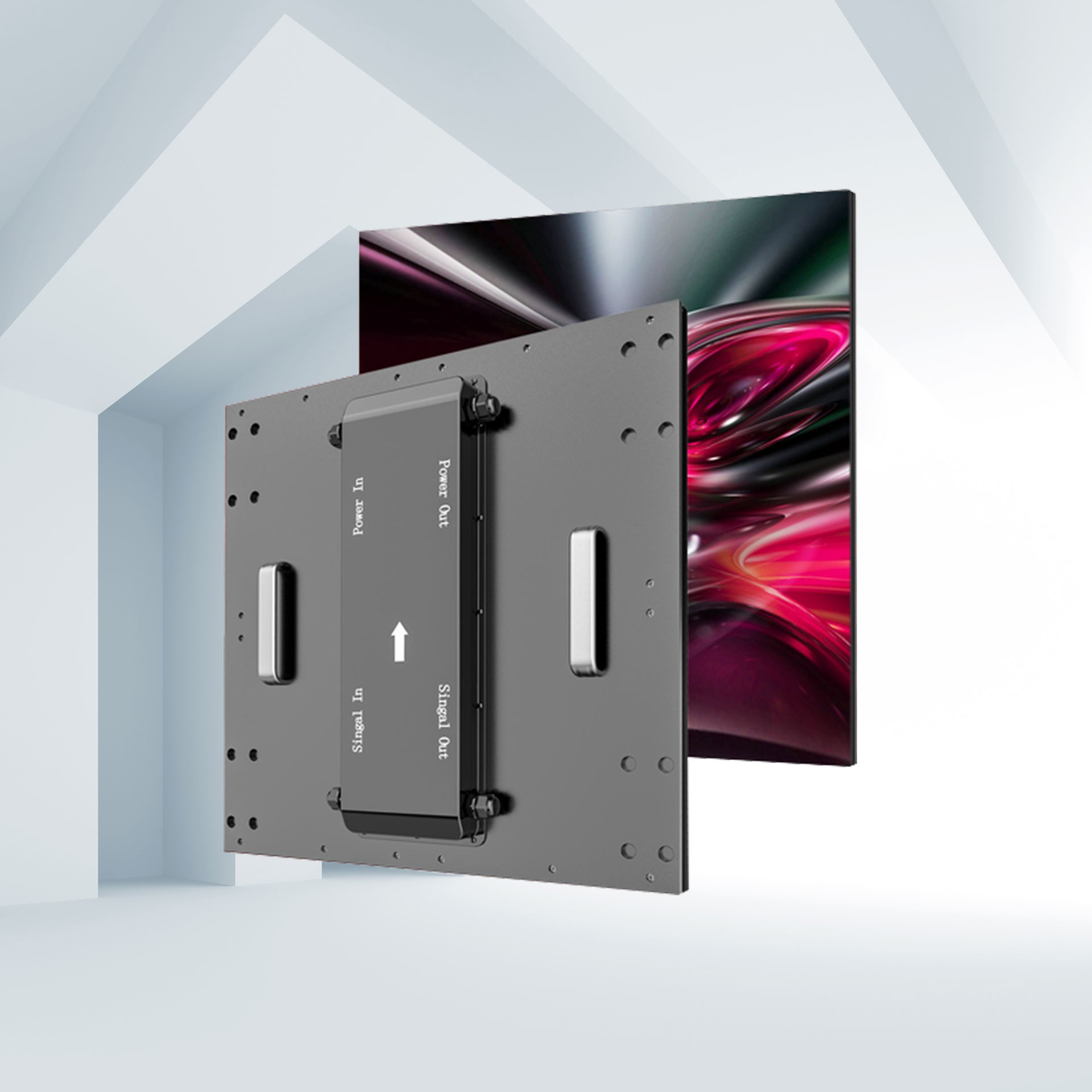
Typical components:
Video source (server, media player).
Sending card(s) (transmitters) in the server or external.
Receiving card(s) inside the cabinets.
Display controller or video processor for scaling, edge blending, and input management.
Optional GPU or dedicated graphics card for high-density content and multi-screen outputs.
Map channels so each sending card outputs to the correct group of receiving cards. Verify data cable type (Ethernet fiber, Cat6, proprietary) and maximum cable length.
Calculate power per cabinet and total system power.
Provide breakers, distribution layout, and redundancy (N+1) if required.
Model heat dissipation and airflow. For outdoor installations include sun/shade effects.
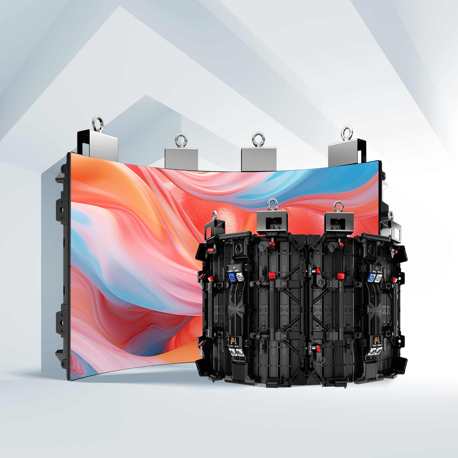
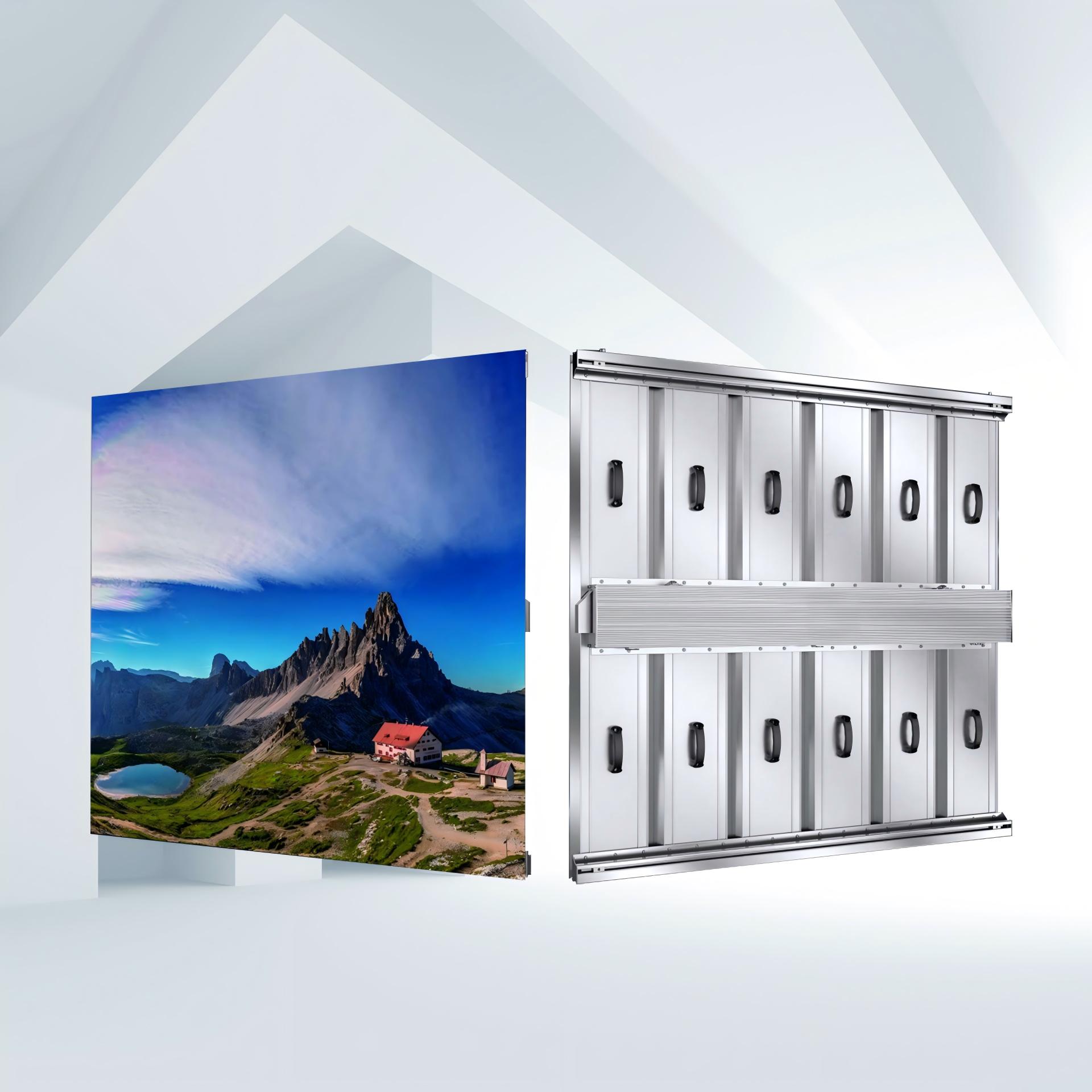
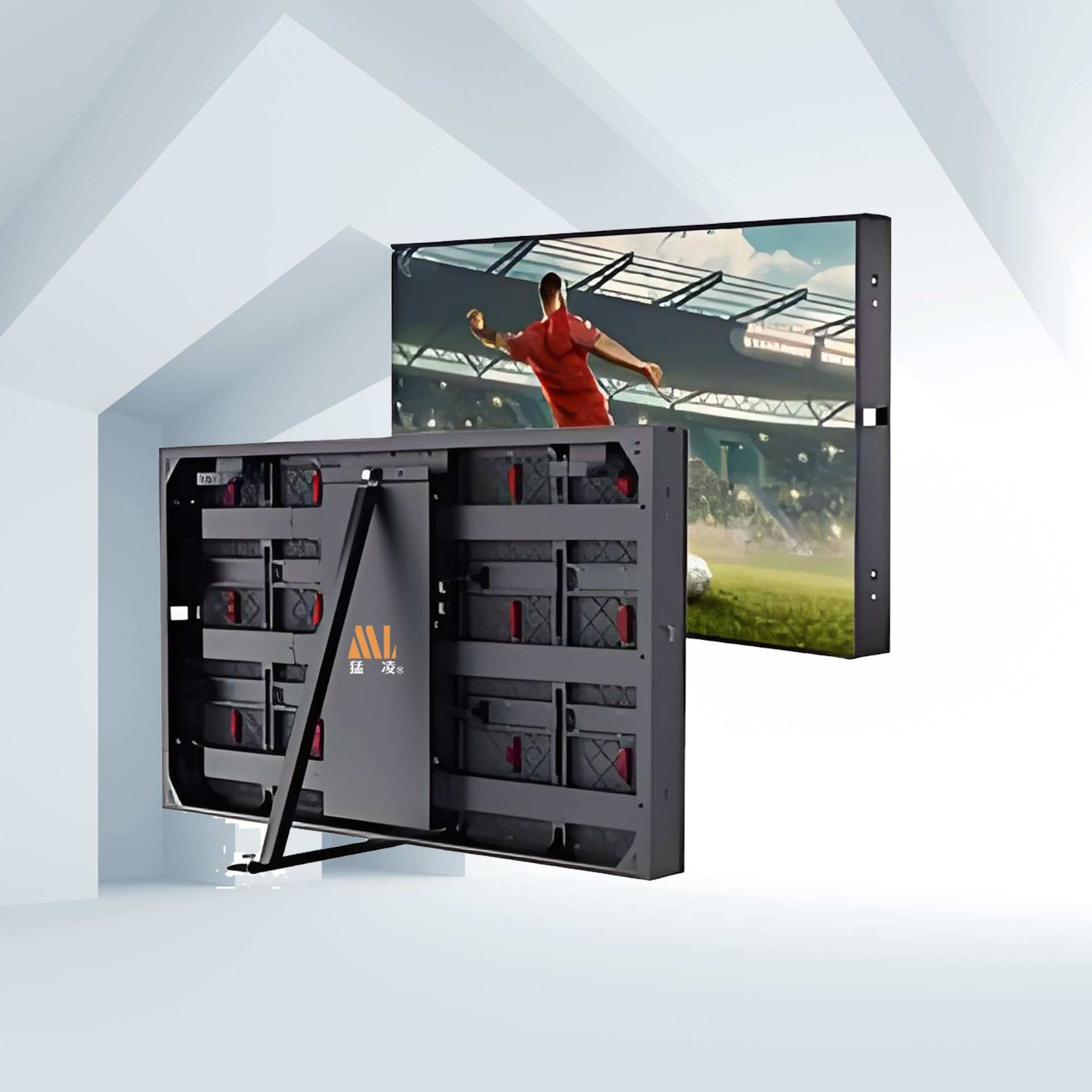
Mounting frame drawings and lifting points.
Cabinet tolerances and gasketing for weatherproofing.
Access for service panels and module replacement.
Safety attachments, grounding, and lightning protection.
Provide a concise cost breakdown for quotation.
Total Price = Cost(screen panels & cabinets) + Cost(sending card(s)) + Cost(receiving card(s)) + Cost(GPU / video processor / control system) + Cost(accessories) + Installation & shipping + Contingency
Accessories typically include power distribution, cabling, mounting frame, network switches, weather sealing, spare modules, and on-site tools.
Technical drawings and BOM.
Pixel map and receiving card map.
Power schedule and breaker sizing.
Installation sequence and lead times.
Warranty and service SLA.
Chosen module: 160 mm × 160 mm, 16 × 16 pixels.
Modules (W × H): 48 × 36.
Installed area: 44.2368 m².
Resolution: 768 × 576 pixels (442,368 pixels).
Receiving cards required: 14 (based on 256 × 128 pixels per card).
Next steps: finalize cabinet count, confirm receiving card model, run power calculations, prepare BOM and installation drawing.

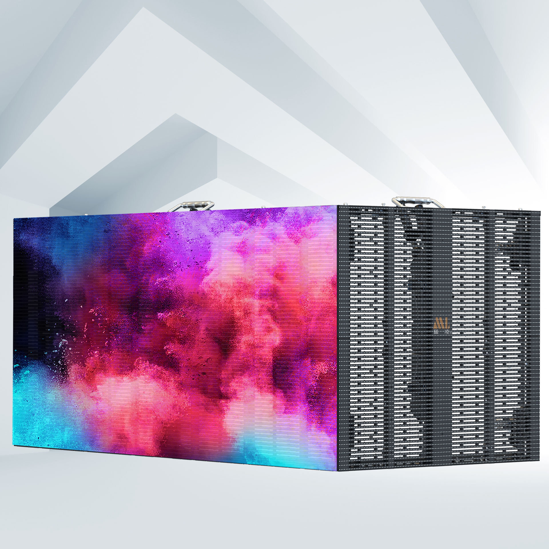
Mengling is a global provider of LED displays. We show premium technology with cutting-edge technology and advanced innovations, providing LED display products, solutions,and services worldwide for rental stage events, ads billboards, commercial display, etc.
Building 1, Zhongzhan Technology Park, No. 9 Furong Road, Tantou Community, Songgang Street, Shenzhen
0755-2301-1202
info@mightyling.com
Factory Address:
No. 1 Factory Building 101, Phase Ⅱ of Jinshunyuan Factory Area, Songgang Street, Bao'an District, Shenzhen, China